Type N Male Connector for 1/2 inch Cables
Type N Male Connector for 1/2 inch Cables
Buy Now, Pay Later with No Interest if paid in full within 6-12 months. Choose Klarna payment option at the checkout for details of this, and other long-term low-interest financing options.
Free Lifetime Support. SKU / Model: AFCL4TNM-PSA


1(855)846-2654
Need installation quote, or help with designing a custom solution? Submit a request for quote.
- Description
- Reviews
- Questions & Answers
- Make An Offer
- Warning
Description
Product Description
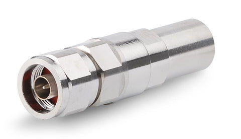
N-Male Positive Stop for half inch coaxial cables is SignalBooster.com's premium 50 Ohm impedance silver N Male crimp connector for half inch diameter low density foam (LDF) cables. It is extremely durable, and backed by ten years warranty. This wireless radiating RF connector's body style is straight. It fits cables such as our Premium 1/2" Plenum Air Aluminum Cable. 1/2 inch N Male Positive Stop for AL4RPV, LDF4 & HL4RP-50 cables.
Featuring a body plated with tri-metals, the Andrew N male positive stop L4TNM-PSA is designed for compatible products including LDF4-50, AL4RPV-50, and HL4RP-50. With a silver-plated, self-captivated self-flare center pin, the product features, and impedance of 50 ohms frequency range between 0.0 gigahertz and 8.8 gigahertz. The RF connector type is N male and the style of the RF connector body is straight.
Electrical Specifications:
| Connector Impedance | 50 ohm |
|---|---|
| Operating Frequency Band | 0 – 8800 MHz |
| Cable Impedance | 50 ohm |
| 3rd Order IMD, typical | -116 dBm @ 910 MHz |
| 3rd Order IMD Test Method | Two +43 dBm carriers |
| RF Operating Voltage, maximum (vrms) | 707.00 V |
| dc Test Voltage | 2000 V |
| Outer Contact Resistance, maximum | 0.30 mOhm |
| Inner Contact Resistance, maximum | 2.00 mOhm |
| Insulation Resistance, minimum | 5000 MOhm |
| Average Power | 0.6 kW @ 900 MHz |
| Peak Power, maximum | 10.00 kW |
| Insertion Loss, typical | 0.05 dB |
| Shielding Effectiveness | -130 dB |
Mechanical Specifications:
| Outer Contact Attachment Method | Ring-flare |
|---|---|
| Inner Contact Attachment Method | Captivated |
| Outer Contact Plating | Trimetal |
| Inner Contact Plating | Silver |
| Attachment Durability | 25 cycles |
| Interface Durability | 1500 cycles |
| Interface Durability Method | IEC 61169-16:9.5 |
| Connector Retention Tensile Force | 890 N | 200 lbf |
| Connector Retention Torque | 5.42 N-m | 48.00 in lb |
| Insertion Force | 66.72 N | 15.00 lbf |
| Insertion Force Method | MIL-C-39012C-3.12, 4.6.9 |
| Coupling Nut Proof Torque | 4.52 N-m | 40.00 in lb |
| Coupling Nut Retention Force | 444.82 N | 100.00 lbf |
| Coupling Nut Retention Force Method | MIL-C-39012C-3.25, 4.6.22 |
Dimensions:
| Nominal Size | 1/2 inch |
|---|---|
| Diameter | 0.88 inch |
| Length | 3.02 inches |
| Weight | 0.21 lb |
Environmental Specifications:
| Operating Temperature | -67 °F to +185 °F |
|---|---|
| Storage Temperature | -67 °F to +185 °F |
| 24 hrs Immersion Depth | 1 meter |
| Immersion Test Mating | Unmated |
| Immersion Test Method | IEC 60529:2001, IP68 |
| Water Jetting Test Mating | Unmated |
| Water Jetting Test Method | IEC 60529:2001, IP66 |
| Moisture Resistance Test Method | MIL-STD-202F, Method 106F |
| Mechanical Shock Test Method | MIL-STD-202, Method 213, Test Condition I |
| Thermal Shock Test Method | MIL-STD-202F, Method 107G, Test Condition A-1, Low Temperature -55 °C |
| Vibration Test Method | IEC 60068-2-6 |
| Corrosion Test Method | MIL-STD-1344A, Method 1001.1, Test Condition A |
Return Loss/ VSWR:
| Frequency Band / VSWR / Return Loss (dB) | 45–1000 MHz / 1.02 / 39.00 |
|---|---|
| Frequency Band / VSWR / Return Loss (dB) | 1010–2200 MHz / 1.03 / 37.00 |
| Frequency Band / VSWR / Return Loss (dB) | 2210–3000 MHz / 1.05 / 33.00 |
| Frequency Band / VSWR / Return Loss (dB) | 3010–4000 MHz / 1.09 / 27.00 |
| Frequency Band / VSWR / Return Loss (dB) | 4010–6000 MHz / 1.25 / 19.00 |
| Frequency Band / VSWR / Return Loss (dB) | 6010–8000 MHz / 1.33 / 17.00 |
Regulatory Compliance/ Certifications:
| Agency: Classification | RoHS 2011/65/EU: Compliant by Exemption |
|---|---|
| Agency: Classification | China RoHS SJ/T 11364-2006: Above Maximum Concentration Value (MCV) |
| Agency: Classification | ISO 9001:2008: Designed, manufactured and/or distributed under this quality management system |
1/2" Plenum N-Type Male Positive Stop Connector.
Reviews
Questions & Answers
QUESTIONS & ANSWERS
Have a Question?
Be the first to ask a question about this.
Data Sheet / User Guide
Make An Offer
Warning
Note: For any signal booster to help, outside signal strength must be at least -110 dB or there must be a clear line of sight to a cell tower that is within twenty miles. Before ordering, please check outside signal level in decibels or ensure that you can make and hold a phone call at any good spot outside where you can mount an exterior antenna. Square footage stated in signal booster listings is based on good signal outside. If it is any weaker, the boosted sq. ft. area will be considerably lower, accordingly.
Kevin K. of Anderson, California gave the following review:
Website is easy to use with plain straight forward info but could have had more on testing signal strength to make sure you get a strong enough booster.
Therefore, please note that stated sq. ft. coverage is based on good signal outside. For best results: If outside signal is weak, we suggest choosing the next higher sq. ft. coverage kit. If outside signal is very weak, we suggest choosing the kit with even more higher sq. ft. range bracket. Basically, higher the sq. ft. bracket, the more powerful the signal amplifier with greater Gain as well as higher uplink and downlink output power.
If outside signal is too weak (weaker than -110 dB), submit request for cell coverage solution assessment. Upon receipt of questionnaire, we will perform residential or business site survey. This will help us determine the system that is needed to improve cell coverage. Then, we will create system design using that system such as femtocell, active or hybrid distributed antenna system (DAS), or other carrier feed signal enhancing method available that will work at your signal-challenged location. Finally, we will schedule for installation after equipment and installation service quote has been approved by you, or your company.
For non installation-included kits: Most home / office / building cell signal booster kits only include bracket to mount exterior antenna on outside wall, edge of roof, or existing pipe up to 2 inches in diameter. Mounting pole not included with most kits, unless stated specifically that it is included for free. Therefore, a mounting post must be purchased separately if you will require it to mount exterior antenna.

Related Products