1/2" Air Heliax Plenum Air Dielectric 50 Ohm Coax Red Cable Per Foot
1/2" Air Heliax Plenum Air Dielectric 50 Ohm Coax Red Cable Per Foot
Buy Now, Pay Later with No Interest if paid in full within 6-12 months. Choose Klarna payment option at the checkout for details of this, and other long-term low-interest financing options.
Free Lifetime Support. SKU / Model: AL4RPV-50R


1(855)846-2654
Need installation quote, or help with designing a custom solution? Submit a request for quote.
- Description
- Reviews
- Questions & Answers
- Make An Offer
- Warning
Description
Product Description
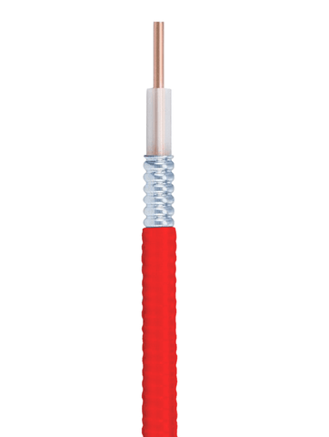
This is a half inch thick diameter Heliax Plenum Air Dielectric coaxial cable. It is red in color. It has 50 Ohm impedance. It is sold by the foot. It is manufactured by Andrew antenna & wire company that is now owned by CommScope communication infrastructure company. Item name: HELIAX Plenum Rated Air Dielectric Coaxial Cable, corrugated aluminum, 1/2 inch, Red PVC jacket. SKU: AL4RPV-50R.
These frequency signal transmitting coax cables are used in systems such as cell phone signal booster, repeater, distributed antenna system (DAS), bidirectional amplifier (BDA) systems, etc. to connect antennas with system components such as cellular amplifier main base unit. Prep tool and cable connector(s) not included with purchase. They must be purchased separately, as needed.
Please Note: This half an inch thick coax. cable is available in bulk and is priced per foot because it is sold by the foot. Therefore, after adding this item to cart, please update "quantity" in shopping cart based upon number of feet required.
General Specifications:
| Flexibility | Standard. |
|---|---|
| Jacket Color | Red. |
Dimensions:
| Diameter Over Dielectric | 12.954 mm | 0.51 in. |
|---|---|
| Diameter Over Jacket | 15.748 mm | 0.62 in. |
| Inner Conductor OD | 4.572 mm | 0.18 in. |
| Outer Conductor OD | 14.046 mm | 0.553 in. |
| Nominal Size | 1/2 inch. |
Electrical Specifications:
| Cable Impedance | 50 ohm ±1 ohm. |
|---|---|
| Capacitance | 75.459 pF/m | 23 pF/ft. |
| dc Resistance, Inner Conductor | 0.48 ohms/kft | 1.575 ohms/km. |
| dc Resistance, Outer Conductor | 0.48 ohms/kft | 1.575 ohms/km. |
| dc Test Voltage | 4000 V. |
| Inductance | 0.19 µH/m | 0.058 µH/ft. |
| Insulation Resistance | 100000 MOhms-km. |
| Jacket Spark Test Voltage (rms) | 5000 V. |
| Operating Frequency Band | 1 – 6000 MHz. |
| Peak Power | 40 kW. |
| Power Attenuation | 2.325000047683716. |
| Pulse Reflection | 0.5%. |
| Velocity | 88 %. |
Attenuation:
| Frequency 1 MHz | Attenuation (dB/100 ft) = 0.066; Average Power (kW) = 35.37. |
|---|---|
| Frequency 1.5 MHz | Attenuation (dB/100 ft) = 0.081; Average Power (kW) = 28.84. |
| Frequency 2 MHz | Attenuation (dB/100 ft) = 0.093; Average Power (kW) = 24.95. |
| Frequency 10 MHz | Attenuation (dB/100 ft) = 0.211; Average Power (kW) = 11.04. |
| Frequency 20 MHz | Attenuation (dB/100 ft) = 0.300; Average Power (kW) = 7.75. |
| Frequency 30 MHz | Attenuation (dB/100 ft) = 0.370; Average Power (kW) = 6.29. |
| Frequency 50 MHz | Attenuation (dB/100 ft) = 0.482; Average Power (kW) = 4.83. |
| Frequency 85 MHz | Attenuation (dB/100 ft) = 0.636; Average Power (kW) = 3.66 |
| Frequency 88 MHz | Attenuation (dB/100 ft) = 0.648; Average Power (kW) = 3.59. |
| Frequency 100 MHz | Attenuation (dB/100 ft) = 0.693; Average Power (kW) = 3.35. |
| Frequency 108 MHz | Attenuation (dB/100 ft) = 0.722; Average Power (kW) = 3.22. |
| Frequency 150 MHz | Attenuation (dB/100 ft) = 0.860; Average Power (kW) = 2.70. |
| Frequency 174 MHz | Attenuation (dB/100 ft) = 0.931; Average Power (kW) = 2.50. |
| Frequency 200 MHz | Attenuation (dB/100 ft) = 1.003; Average Power (kW) = 2.32. |
| Frequency 204 MHz | Attenuation (dB/100 ft) = 1.014; Average Power (kW) = 2.29. |
| Frequency 300 MHz | Attenuation (dB/100 ft) = 1.251; Average Power (kW) = 1.86. |
| Frequency 400 MHz | Attenuation (dB/100 ft) = 1.465; Average Power (kW) = 1.59. |
| Frequency 450 MHz | Attenuation (dB/100 ft) = 1.565; Average Power (kW) = 1.49. |
| Frequency 460 MHz | Attenuation (dB/100 ft) = 1.584; Average Power (kW) = 1.47. |
| Frequency 500 MHz | Attenuation (dB/100 ft) = 1.659; Average Power (kW) = 1.40. |
| Frequency 512 MHz | Attenuation (dB/100 ft) = 1.682; Average Power (kW) = 1.38. |
| Frequency 600 MHz | Attenuation (dB/100 ft) = 1.839; Average Power (kW) = 1.26. |
| Frequency 700 MHz | Attenuation (dB/100 ft) = 2.007; Average Power (kW) = 1.16. |
| Frequency 800 MHz | Attenuation (dB/100 ft) = 2.166; Average Power (kW) = 1.07. |
| Frequency 824 MHz | Attenuation (dB/100 ft) = 2.203; Average Power (kW) = 1.06. |
| Frequency 894 MHz | Attenuation (dB/100 ft) = 2.308; Average Power (kW) = 1.01. |
| Frequency 960 MHz | Attenuation (dB/100 ft) = 2.405; Average Power (kW) = 0.97. |
| Frequency 1000 MHz | Attenuation (dB/100 ft) = 2.463; Average Power (kW) = 0.94. |
| Frequency 1218 MHz | Attenuation (dB/100 ft) = 2.764; Average Power (kW) = 0.84. |
| Frequency 1250 MHz | Attenuation (dB/100 ft) = 2.806; Average Power (kW) = 0.83. |
| Frequency 1500 MHz | Attenuation (dB/100 ft) = 3.126; Average Power (kW) = 0.74. |
| Frequency 1700 MHz | Attenuation (dB/100 ft) = 3.369; Average Power (kW) = 0.69. |
| Frequency 1794 MHz | Attenuation (dB/100 ft) = 3.480; Average Power (kW) = 0.67. |
| Frequency 1800.0 MHz | Attenuation (dB/100 ft) = 3.487; Average Power (kW) = 0.67. |
| Frequency 2000 MHz | Attenuation (dB/100 ft) = 3.716; Average Power (kW) = 0.63. |
| Frequency 2100 MHz | Attenuation (dB/100 ft) = 3.828; Average Power (kW) = 0.61. |
| Frequency 2200 MHz | Attenuation (dB/100 ft) = 3.938; Average Power (kW) = 0.59. |
| Frequency 2300 MHz | Attenuation (dB/100 ft) = 4.046; Average Power (kW) = 0.57. |
| Frequency 2500 MHz | Attenuation (dB/100 ft) = 4.259; Average Power (kW) = 0.55. |
| Frequency 2700 MHz | Attenuation (dB/100 ft) = 4.467; Average Power (kW) = 0.52. |
| Frequency 3000 MHz | Attenuation (dB/100 ft) = 4.770; Average Power (kW) = 0.49. |
| Frequency 3400 MHz | Attenuation (dB/100 ft) = 5.159; Average Power (kW) = 0.45. |
| Frequency 3600 MHz | Attenuation (dB/100 ft) = 5.349; Average Power (kW) = 0.43. |
| Frequency 3700 MHz | Attenuation (dB/100 ft) = 5.443; Average Power (kW) = 0.43. |
| Frequency 3800 MHz | Attenuation (dB/100 ft) = 5.536; Average Power (kW) = 0.42. |
| Frequency 3900 MHz | Attenuation (dB/100 ft) = 5.628; Average Power (kW) = 0.41. |
| Frequency 4000 MHz | Attenuation (dB/100 ft) = 5.720; Average Power (kW) = 0.41. |
| Frequency 4100 MHz | Attenuation (dB/100 ft) = 5.811; Average Power (kW) = 0.40. |
| Frequency 4200 MHz | Attenuation (dB/100 ft) = 5.902; Average Power (kW) = 0.39. |
| Frequency 4300 MHz | Attenuation (dB/100 ft) = 5.991; Average Power (kW) = 0.39. |
| Frequency 4400 MHz | Attenuation (dB/100 ft) = 6.081; Average Power (kW) = 0.38. |
| Frequency 4500 MHz | Attenuation (dB/100 ft) = 6.169; Average Power (kW) = 0.38. |
| Frequency 4600 MHz | Attenuation (dB/100 ft) = 6.257; Average Power (kW) = 0.37. |
| Frequency 4700 MHz | Attenuation (dB/100 ft) = 6.345; Average Power (kW) = 0.37. |
| Frequency 4800 MHz | Attenuation (dB/100 ft) = 6.432; Average Power (kW) = 0.36. |
| Frequency 4900 MHz | Attenuation (dB/100 ft) = 6.519; Average Power (kW) = 0.36. |
| Frequency 5000 MHz | Attenuation (dB/100 ft) = 6.605; Average Power (kW) = 0.35. |
| Frequency 6000 MHz | Attenuation (dB/100 ft) = 7.443; Average Power (kW) = 0.31. |
Return Loss & VSWR:
| Frequency Band 700–894 MHz | VSWR = 1.13; Return Loss (dB) = 24.30 |
|---|---|
| Frequency Band 806–960 MHz | VSWR = 1.13; Return Loss (dB) = 24.30 |
| Frequency Band 1700–2200 MHz | VSWR = 1.13; Return Loss (dB) = 24.30 |
Material Specifications:
| Dielectric Material | PE spline. |
|---|---|
| Jacket Material | PVC. |
| Inner Conductor Material | Copper-clad aluminum wire. |
| Outer Conductor Material | Corrugated aluminum. |
Mechanical Specifications:
| Minimum Bend Radius, multiple Bends | 127 mm | 5 in. |
|---|---|
| Minimum Bend Radius, Single Bend | 63.5 mm | 2.5 in. |
| Number of Bends, minimum | 15. |
| Tensile Strength | 79 kg | 174.165 lb. |
| Bending Moment | 6.779 N-m | 5 ft lb. |
| Flat Plate Crush Strength | 1.429 kg/mm | 80 lb/in. |
Environmental Specifications:
| Installation temperature | -5 °C to +60 °C (+23 °F to +140 °F). |
|---|---|
| Operating Temperature | -20 °C to +85 °C (-4 °F to +185 °F). |
| Storage Temperature | -20 °C to +85 °C (-4 °F to +185 °F). |
| Attenuation, Ambient Temperature | 20 °C | 68 °F. |
| Average Power, Ambient Temperature | 40 °C | 104 °F. |
| Average Power, Inner Conductor Temperature | 100 °C | 212 °F. |
| Fire Retardancy Test Method | NFPA 262/CATVP/CMP. |
Packaging and Weights:
| Cable weight | 0.208 kg/m | 0.14 lb/ft. |
|---|
Regulatory Compliance/Certifications:
| c(ETL)us Certification | CATVP/CMP. |
|---|---|
| ETL Certification | CATVP/CMP. |
| ISO 9001:2015 | Designed, manufactured and/or distributed under this quality management system. |
Reviews
Questions & Answers
QUESTIONS & ANSWERS
Have a Question?
Be the first to ask a question about this.
Data Sheet / User Guide
Make An Offer
Warning
Note: For any signal booster to help, outside signal strength must be at least -110 dB or there must be a clear line of sight to a cell tower that is within twenty miles. Before ordering, please check outside signal level in decibels or ensure that you can make and hold a phone call at any good spot outside where you can mount an exterior antenna. Square footage stated in signal booster listings is based on good signal outside. If it is any weaker, the boosted sq. ft. area will be considerably lower, accordingly.
Kevin K. of Anderson, California gave the following review:
Website is easy to use with plain straight forward info but could have had more on testing signal strength to make sure you get a strong enough booster.
Therefore, please note that stated sq. ft. coverage is based on good signal outside. For best results: If outside signal is weak, we suggest choosing the next higher sq. ft. coverage kit. If outside signal is very weak, we suggest choosing the kit with even more higher sq. ft. range bracket. Basically, higher the sq. ft. bracket, the more powerful the signal amplifier with greater Gain as well as higher uplink and downlink output power.
If outside signal is too weak (weaker than -110 dB), submit request for cell coverage solution assessment. Upon receipt of questionnaire, we will perform residential or business site survey. This will help us determine the system that is needed to improve cell coverage. Then, we will create system design using that system such as femtocell, active or hybrid distributed antenna system (DAS), or other carrier feed signal enhancing method available that will work at your signal-challenged location. Finally, we will schedule for installation after equipment and installation service quote has been approved by you, or your company.
For non installation-included kits: Most home / office / building cell signal booster kits only include bracket to mount exterior antenna on outside wall, edge of roof, or existing pipe up to 2 inches in diameter. Mounting pole not included with most kits, unless stated specifically that it is included for free. Therefore, a mounting post must be purchased separately if you will require it to mount exterior antenna.

Related Products